Showing posts with label Electronics. Show all posts

Sunday, 3 November 2019

Magic Wand: Charlieplexing LEDs

Introduction

My daughter wanted to be a witch for Halloween. For that costume was of course a Magic Wand a mandatory accessory.

The finished Magic Wand
I try to give some information about how I have made this toy in this blog post.
I have made a movie to show the different patterns, but I noticed that the sound was not correct. This will be reuploaded at a later time.

 There is a debug interface to upload new firmware to the magic wand.

Mechanical construction

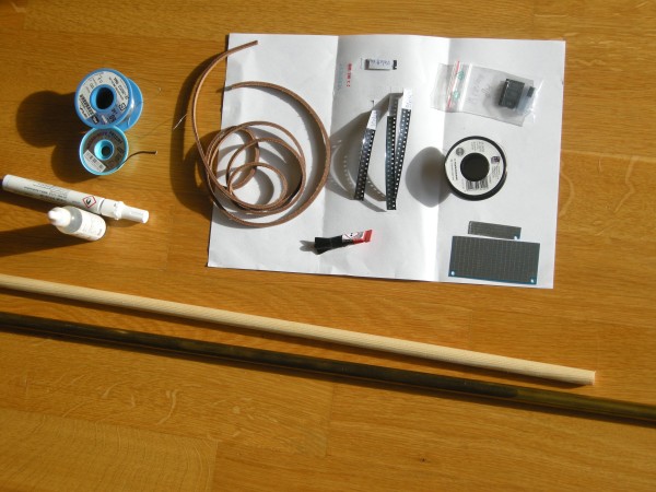
The following picture shows the main items I have used to make the magic wand: 
  • As base I have used a 12mm diameter wooden stick.
  • To store the electronics and batteries I have used a brass tube with an inner diameter of about the same as the outer diameter of the wood. With a bit Kapton tape is the stick stuck in the tube. This part forms the handle of the magic wand. It is also possible to use an empty tube like part such as a (whiteboard) marker.
  • A leather cord is glued to the handle to make it feel and look nice.
  • LEDs are glued with super glue to the wood before soldering the wire to each LED.  I have used 0603 for the body of the wand and 0805 for the top.  In my case I have used the colour purple for all led.
  • The electronics consist of mainly a Attiny84 with some resistors and capacitors.  
  • The chip is soldered on a piece of SMD prototype board. This has a bit of a special grid and was not perfect in that aspect but it was very thin and could be easily cut to size and fixed in the wood & tube.  I have used this.
  • The LED and electronics are connected with a 0.2mm diameter isolated copper wire. The isolation layer is burned off on the locations where I wanted to solder.
  • Paint and lacquer to colour the stick. I have used acrylic paint.
  • Furthermore is solder, flux and solder wick needed.
I have a few tips on the assembly:
  • It is difficult to get the stick in the right shape.  Clamping the stick in a drill and run it over sanding paper did not work so well.  Cutting it with plane in the right shape and sanding afterwards did work for me.  A small lathe is probably nice for this kind of round work pieces.
  • The super glue worked very well to tack the led to the wood and to solder it. A bit heat is needed to remove the glue from the led on the points where it should be soldered. But no led came of during the soldering.
  • With the solder iron on 450C is the isolation material on the copper wire quickly gone. This works better than a mechanical method (sanding paper, knife etc.) however is not good for the tip of the soldering iron.
  • I have painted clear lacquer over the LEDs after the soldering; this to protect the led and the wires. A disadvantage of this is that the light travels side ways over the magic wand. 
  • I have put first the 8 wires on the stick with tape and then put the LEDs in between and have solder them by pulling the wire to the LED.  Probably it is easier to put lines on the stick to determine the LED position, glue the led and then pull the wires from LED to led. I expect that that works better to keep things nicely oriented. 

Electrical schematic


The electrical schematic is fairly simple. PortA of the Attiny84 microcontroller is used to drive the leds.  In principle is it possible to charlieplex in this way 56 leds (N^2-N). For this design I am using only 24 leds.  The 150ohm resistors is calculated based on a 2.8V voltage drop over the led and a 5mA drive current. In the software is never more then 1 led on at the same time so this construction is from the current load on the microcontroller fairly uncritical.
Electrical schematic of the Magic Wand
The the size of the LEDs on the body of the stick are 0603 and on the top is 0805 used.
The programming interface is working correctly when the LEDs are attached.  This does give some additional light effects when the microcontroller is programmed.
The push button is directly between the batteries and the processor board.  For testing I have used 3 AAA penlight batteries. I have used 3 stacked LR44 batteries to fit in the handle during "normal" usage.  The electrical contact points of the battery are made with thumb-tacks, which works surprisingly well.  The diode D1 protects the circuit when I forget what the + and - side of the battery should be.

With some work the electronics looks like this:
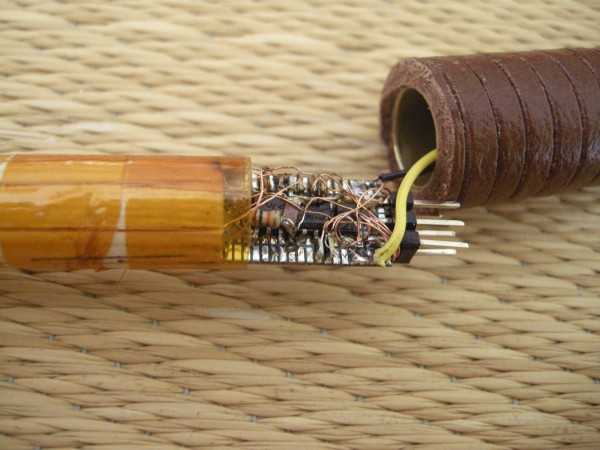
The electronics inside the magic wand.
The black wire is the (-) of the battery and the yellow the (+). The 6pin AVR ISP connector is clearly visible. The 0.2mm diameter copper wires are thin compared with the other parts.

I had to use a microscope to solder this successfully.

Software 

The firmware for the magic wand is fairly simple and written in the Arduino platform.  There is no real reason to do this; this could be done just as simple without Arduino and with a normal Makefile and avr-gcc.

A table with DDRA and PORTA values is used to address each LED correctly and to compensate for "errors" in the soldering.  By using the index in the table is each LED addressable.

The push button is connected to the power supply of the Attiny84. This means that when the button is pushed the processor gets power and comes out of the reset.  As first step is the previous animation number read out of the EEprom.
Then is the next animation shown. At the end of the animation is this new number written into the EEprom.
After this is the processor put in deep sleep to save current when the button is continuously pushed.

With this setup is it possible to repeat an animation when the button is released before the animation is finished.  A new animation    will be shown when is waited until the previous animation is finished and the push button is pushed again.

Things to improve:
  • Remove the Arduino frame work.  I am not really using it and it is probably giving some timing issues.
  • I have a flicker in the first part of each animation. Just if it is run two times.  I thought it could be because the calculations done which is adding 0 for the first ring.  But removing this with and IF statement is not solving this either.
  • Some fading or different brightness levels would be nice to add to the animations.  This must be possible with a timer interrupt but I did not had enough time before Halloween to experiment with it.
The source code:
#include <EEPROM.h>   // Items for the EEPROM
#include <avr/sleep.h>    // Sleep Modes
#include <avr/power.h>    // Power management

#define ATTINY84
#define MAXEFFECT 7
#define EEADDRESS 5

#define SLOWCYCLE 200
#define FASTCYCLE 100
#define NULLCYCLE 0

#define SLOWDELAY 400
#define FASTDELAY 200
#define NULLDELAY 3

const uint8_t dirlist[] PROGMEM  ={ B0, 
                  B00000110, B00011000, B01100000, B10000001, B00000011, B00001100, B00110000, B11000000,
                  B00000110, B00011000, B01100000, B10000001, B00000011, B00001100, B00110000, B11000000,
                  B00000101, B00010100, B01010000, B01000001, B00000101, B00010100, B01010000, B01000001 };
const  uint8_t outlist[] PROGMEM  ={ B0, 
                  B00000100, B00010000, B01000000, B00000001, B00000010, B00001000, B00100000, B10000000,
                  B00000010, B00001000, B00100000, B10000000, B00000001, B00000100, B00010000, B01000000,
                  B00000100, B00010000, B01000000, B00000001, B00000001, B00000100, B00010000, B01000000};

struct MyUseCntStruct {
   byte pattern;
   int usecnt;
};

MyUseCntStruct MyUseCnt;

void setup() {
  // put your setup code here, to run once:
   SetLed(0);
   EEPROM.get(EEADDRESS, MyUseCnt);
   MyUseCnt.pattern +=1;
   if (MyUseCnt.pattern > MAXEFFECT) MyUseCnt.pattern=0;  
}

void loop() {
  // put your main code here, to run repeatedly:
  switch (MyUseCnt.pattern) {
    case 0: 
       PatternDot();
       break;
    case 1:
       PatternRing();
       break;
    case 2:
        AllOn();
        break;
    case 3:
        TestRing();
        break;
    case 4:
        PatternLine1();
        break;
    case 5:
        PatternLine2();
        break;
    case 6:
        PatternRandom();
        break;
    case 7:
        PatternRing2();
        break;    
    default:
       PatternDot();
       break;
    }
 MyHalt();
}

void SetLed(uint8_t lednum) {
  PORTA=0; // Set all to zero before changing the led
  DDRA=pgm_read_byte_near(dirlist + lednum);
  PORTA=pgm_read_byte_near(outlist + lednum);
}

void MyHalt() {
  // function to stop the anymation and to put the processor to sleep
  SetLed(0);
  set_sleep_mode(SLEEP_MODE_PWR_DOWN);
  MyUseCnt.usecnt+=1;
  EEPROM.put(EEADDRESS, MyUseCnt);
  // now sleep
  ADCSRA = 0;            // ADC ausschalten
  power_all_disable (); 
  sleep_enable();
  sleep_cpu();             // µC schläft     
}

void RingLed(uint8_t ring, uint16_t cycle, uint16_t wait) {
  // Make a ring light
  // 0 is the ring closed to the handle and 5 is the ring at the tip.
  if (ring == 0) {
    for (uint16_t i = 0; i <= cycle; i++) {
       SetLed(1 );
       delay(wait);
       SetLed(2 );
       delay(wait);
       SetLed(3 );
       delay(wait);
       SetLed(4);
       delay(wait);
    }    
  } else {
    ring *= 4;
    for (uint16_t i = 0; i <= cycle; i++) {
       SetLed(1 + ring );
       delay(wait);
       SetLed(2 + ring );
       delay(wait);
       SetLed(3 + ring );
       delay(wait);
       SetLed(4 + ring );
       delay(wait);
    }
  }
}

void ColumLed(uint8_t column, uint16_t cycle, uint16_t wait) {
  // Make a column on the stick
  if (column ==0 ) {
      for (uint16_t i = 0; i <= cycle; i++) {
         SetLed(1);
         delay(wait);
         SetLed(5);
         delay(wait);
         SetLed(9);
         delay(wait);
         SetLed(13);
         delay(wait);
         SetLed(17);
         delay(wait);
         SetLed(21);
         delay(wait);
      }
  } else {
    for (uint16_t i = 0; i <= cycle; i++) {
       SetLed(1 + column );
       delay(wait);
       SetLed(5 + column );
       delay(wait);
       SetLed(9 + column );
       delay(wait);
       SetLed(13 + column );
       delay(wait);
       SetLed(17 + column );
       delay(wait);
       SetLed(21 + column );
       delay(wait);
    }
  }
}

void PatternDot () {
  RingLed(0,NULLCYCLE,FASTDELAY);
  RingLed(1,NULLCYCLE,FASTDELAY);
  RingLed(2,NULLCYCLE,FASTDELAY);
  RingLed(3,NULLCYCLE,FASTDELAY);
  RingLed(4,NULLCYCLE,FASTDELAY);
  RingLed(5,NULLCYCLE,FASTDELAY);
  RingLed(5,SLOWCYCLE,NULLDELAY);
}

void PatternRing() {
  RingLed(0,FASTCYCLE,NULLDELAY);
  RingLed(1,FASTCYCLE,NULLDELAY);
  RingLed(2,FASTCYCLE,NULLDELAY);
  RingLed(3,FASTCYCLE,NULLDELAY);
  RingLed(4,FASTCYCLE,NULLDELAY);
  RingLed(5,SLOWCYCLE,NULLDELAY);
}

void PatternRing2() {
  RingLed(0,FASTCYCLE,NULLDELAY);
  RingLed(1,FASTCYCLE/2,NULLDELAY);
  RingLed(2,FASTCYCLE/3,NULLDELAY);
  RingLed(3,FASTCYCLE/4,NULLDELAY);
  RingLed(4,FASTCYCLE/5,NULLDELAY);
  RingLed(5,SLOWCYCLE,NULLDELAY);
}
  
void TestRing() {
  RingLed(5, SLOWCYCLE,NULLDELAY);
}

void AllOn() {
  for (uint16_t i = 0; i <= FASTCYCLE; i++) {
    RingLed(0, NULLCYCLE,NULLDELAY);
    RingLed(1, NULLCYCLE,NULLDELAY);
    RingLed(2, NULLCYCLE,NULLDELAY);
    RingLed(3, NULLCYCLE,NULLDELAY);
    RingLed(4, NULLCYCLE,NULLDELAY);
    RingLed(5, NULLCYCLE,NULLDELAY);
  }
  RingLed(5, SLOWCYCLE,NULLDELAY);
}

void PatternLine1() {
   ColumLed(0,NULLCYCLE, FASTDELAY);
   ColumLed(1,NULLCYCLE, FASTDELAY);
   ColumLed(2,NULLCYCLE, FASTDELAY);
   ColumLed(3,NULLCYCLE, FASTDELAY);
   RingLed(5, SLOWCYCLE,NULLDELAY);
}

void PatternLine2() {
   ColumLed(0,FASTCYCLE, NULLDELAY);
   ColumLed(1,FASTCYCLE, NULLDELAY);
   ColumLed(2,FASTCYCLE, NULLDELAY);
   ColumLed(3,FASTCYCLE, NULLDELAY);
   RingLed(5, SLOWCYCLE, NULLDELAY);
}

void PatternRandom() {
    SetLed(1);
    delay(FASTDELAY/2);
    SetLed(10);
    delay(FASTDELAY/2);
    SetLed(7);
    delay(FASTDELAY/2);
    SetLed(3);
    delay(FASTDELAY/2);
    SetLed(15);
    delay(FASTDELAY/2);
    SetLed(17);
    delay(FASTDELAY/2);
    SetLed(4);
    delay(FASTDELAY/2);    
    SetLed(10);
    delay(FASTDELAY/2);    
    SetLed(2);
    delay(FASTDELAY/2);
    SetLed(18);
    delay(FASTDELAY/2);    
    SetLed(9);
    delay(FASTDELAY/2);    
    SetLed(9);
    delay(FASTDELAY/2);    
    RingLed(5, SLOWCYCLE, NULLDELAY);
}
Saturday, 27 October 2018

Terratec Producer Phase 24FW digital / midi connector pin-out.

I started recently to look into "professional" audio interfaces for Linux. As part of this I have picked up from ebay a Terratec Producer Phase 24 FW in my quest for decent equipment . This is a fairly simple interface with 2 analogue inputs and 4 analogue outputs of which 2 are used for the headpones output at the front of the box.  There are two nice things of this box:
  • Fully supported by the FFADO project.
  • 24bit resolution with 192kHz sample rate.
There is now-a-days not much information to find about this box. There are some old reviews, but the normal website of Terratec is not showing much anymore. However there is a kind of manual archive with some good information and software. This can be found here. The software is of course MAC and windows only and therefore not so important.

Unfortunately the box came without the adapter cable for the digital connector.  This connector contains S/PDIF signals and MIDI signals in and out.  I thought I was fine; I don't have MIDI equipment and I did not want to experiment with SPIDF. However at the time I didn't realize that the S/PDIF signal is mandatory to synchronize multiple interfaces together on one master clock.  Some audio interfaces can even use a world clock signal, but most use the optical or coax S/PDIF or ADAT signal for this purpose.

The missing digital and MIDI signal cable as shown on the advertisement material of the manufacturer
Therefore It was necessary to find out the pin-out of the digital 9 pin sub-d connector.  It was fairly easy to guess the function of the pins on the connector by looking at the more or less standard circuits for S/PDIF and MIDI interfaces and by some poking around with a multimeter.

Based on the measurements and the standard schematics I was able to get to the following schematic / cable diagram of a part of the inside of the Phase 24 FW box and the resulting breakout cable:
Terratec Phase 24 FW breakout cable
Schematic of the digital / midi connector and the breakout cable

The inside of the Phase 24 FW part is not very accurate but simplified to understand the way the breakout cable should be connected. There are much more components on the PCB than showed in the above schematic. Interestingly not only the Midi-in is isolated, but also the SPDIF-out is more or less floating. This is probably to prevent ground loops. The suppressor diode tries to keep the excessive voltages under control.

The following table gives an quick overview of the pinning of the 9 pin female sub-d connector on the box:

Signal group
Pin
Description
MID out
1
+5V out through 220Ohm
2
Out signal
3
Gnd
S/PDIF out
4
Signal out
5
Suppressor diode to GND
Midi in
6
LED (diode in parallel with LED) through 220Ohm
7
Return
S/PDIF in
8
82Ohm input
9
Gnd

Looking at the website and other old data of Terratec I expect that the Phase 22 has the same adapter cable for the digital signals.  And it is very well possible that more products use the same pin out for this 9pin sub-d connector.

Now I have to solder a cable and synchronise my audio interfaces.

Tuesday, 25 April 2017

Lab power supply

My new power supply.

For quite some time I have been wanting an adjustable power supply. Both for convenience and hacker credits. Unfortunately, a really good one with all the goodies that I would like to have (multiple outputs, measurements, current limiting, computer control) is somewhere in the €4-to-500 range, which I find a bit too much.

But I still want my fancy power supply!! So I started thinking about making my own. Unfortunately I have no real experience with designing these things. Because of that it seemed a good idea to start with building some kind of kit. This would give me some experience, and possibly give me something to tinker with to see what works and what not.

After some browsing on the Internet I found this kit. It had favourable reviews, and a nice set of features: 0-28V, 0.01-2A, current limiting, short circuit protection,  digital display, current and voltage measurements, all for less than €20!

Of course, I needed to add some other stuff to make it a fully working PSU. A case, heat-sink, fan and banana plug terminals I found on eBay, and a mains switch, mains connector, knobs and a toroidal transformer I bought on-line.  A fuse holder, stand-offs and miscellaneous bits of wire and fasteners came from the well-known pile-of-stuff-that-I-might-need-in-the-future.

Assembling the actual kit was the most straightforward part of the exercise. All parts where there, all through-hole, so no worries at all. The design consists of two boards: an analog board that contains the rectifier, filters and power transistor, and a digital board that has an ATMEGA8, LCD, and two rotary encoders. A ribbon cable connects the two boards, and carries power, two voltage signals coming from the analog board that represent the output current and voltage, and one voltage signal going into the other direction that controls the power transistor. All regulation is done in software, so the ATMEGA monitors the output voltage and current, and adjusts the signal to the power transistor to maintain the correct output. The concept seems very similar to this.

The more involved part of the built actually was the mechanics. Getting a proper case for it, making the right holes in the case, and finding a way to mount everything safely and securely inside. The first case I bought turned out to be a bit too small, so I had to order a new one. As it turned out, that one was actually the same model as in the pictures of the seller of the kit.
First attempt at mounting stuff. In the end I added some stand-offs to the fuse-holder, so it no longer sits directly against the back panel. And I put a bit of anti-slip netting for the transformer to help it to stay put.

For mounting I tried to limit the number of holes in case, for looks, but also very much because any metal parts sticking through the case could potentially carry a large potential in the electrical sense. So I glued some stand-offs behind the front panel of the case to attach the digital board and display. To fix the transformer to the case, I stuck a metal bolt through the plastic lid (of a peanut butter jar), and glued that to the bottom. For glue I used two-component epoxy, which seemed to work reasonably well on the materials involved.

On the back of the case I added a mains connector, and a fuse holder on the inside. The fuse itself caused me some problems. I initially figured that a ~200mA slow fuse should be sufficient. Unfortunately, even 500mA fuses kept blowing during power-up, most likely because the large filter capacitor draws quite some current initially when charging. At the moment, I am using a 1A fuse, which should be good enough to prevent fire, but might not be good enough to prevent the transformer from getting damaged if ever the electronics fail catastrophically.
Everything on the inside. The digital board sits in front, the analog board on the left side, and the transformer on the right.The fan on the heat-sink is triggered by a temperature sensor, and draws air through in the bottom of the case. 

The power supply is able to deliver up to 2A at up to 28V, and can be used in voltage limiting or current limiting mode. It constantly shows the set maximum voltage and current, and what is currently actually delivered. The two rotary knobs change the voltage and current set-points, and pressing a knob stores the set-point as a default. The fan occasionally switches on (triggered by a temperature sensor on the heat-sink), but at least during my typical usage it is hardly ever  needed. So far I am very happy with the power supply. It is especially convenient to be able to see the output current when powering something.

As the ATMEGA8 had two unused pins, it should be possible, in principle, to add a serial interface for controlling it from a computer. This would involve moving some signals around to free up the UART pins, but that is hardly a problem.  Other things on my wish list would be a output enable/disable switch, a mode where the supply switches off when exceeding the current or voltage set-point, and set/used power  (in Watts) on the display, next to current and voltage. I think most of this could be implemented in software, but I would have to start from scratch. Unfortunately, the AVR came already programmed, and the flash memory was locked, so I could not download the software for hacking. I decided to leave these possible improvements for another day,

Anyhow, at the moment I am more than happy enough with the supply as it is. So for now I will spent my time on other projects.


Another view from the top.

Monday, 19 September 2016

Bathroom ventilator upgrade/repair

This was intended to be a simple job involving nothing but simple mechanics and a bit of electrical wiring.

Background

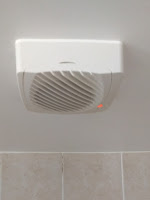
The ventilator. Just in case you were wondering...
Some years ago we had a new ventilator installed in our bathroom. This was a smart fan with a moisture sensor. So if someone was running the shower, the air would get moist, the fan would switch on and extract the air towards outside. As an extra, the unit also had a set of little flaps (a more to the point word probably exists in English) that automatically open and close when the fan starts or stops, and an indicator light, because everyone needs an indicator light.

From the start this thing had the problem of being quite loud. The other family members very much preferred it to stay off while relaxing in the bath. Over time their wish was gradually granted as the fan got more and more slow and finally stopped turning altogether.

Naturally I took the thing apart and checked the motor. Even when hooking it up to mains directly (and yes, it was a 240V part) it did not run anymore. So I got thinking what to do next.

A simple plan

Since the warranty had already run out by a few weeks (duh), I was free to do what I wanted. I figured I could install a new fan as far away from the bathroom as possible in the exhaust chimney thingy on top of the bathroom's roof. So I bought a simple 240V on/off ventilator of similar wattage as the old fan that fitted in the chimney pipe. I would run the wire through the pipe, hook it up to the ventilator controller, and Bob would be my uncle. Easy.

But Murphy was not to be outdone by Bob. While I was thinking this through, buying the ventilator and planning this job, the old ventilator unit failed completely. The flaps no longer opened and the little indicator light stayed dark when running the shower. 

Circuit debugging

The circuit. Note the triac (next to the lamp), and the yellow filtering cap.
The circuit. Note the triac (next to the lamp),
and the yellow filtering cap.
Since I lost the receipt of the new-bought fan, I could not return it to the shop. What was left was to take a good look at the controller circuit. It was pretty simple. It had a triac to switch the mains, a moisture sensor, two adjustable potmeters, a few transistors, diodes and resistors. The transistors were there to get a lower voltage from the mains (I think) and switch the triac when the moisture sensor's resistance would fall below one of the potentiometers. (The other potmeter controlled the time the fan would run before switching off.)

While I am not the most experienced circuit debugger, I know it involves sticking a multimeter in a live circuit. But since this circuit is directly hooked to mains, I would be competing for a Darwin award that way. So I had to try to figure this out without power.

I knew for a fact that the old fan had failed. I also knew that a non-turning motor can draw 2 to 3 times the current compared to when it runs normally. This could potentially overload the controller, causing something to fail.

The only semiconductor in the "240V on" part of the circuit was the Z0103 triac. Some probing with my multimeter also seemed to suggest it was not 100% happy anymore. So I ordered a replacement and let things rest until the new part arrived.

Replacing the triac made the light come back on and the shutters work again! Success! So I did a little dance, kissed my wife, and connected the new fan motor. Disappointment! It showed the same not-really-turning-over behaviour as the old one did towards its end. Clearly something was still wrong with the controller board.

More circuit debugging

Further poking around identified another component in the 240V part of the system: a 0.22μF filter capacitor. For lack of a better idea I took it off and put it in my little component tester: 33nF, about a factor 7 too low. So I ordered a replacement and put the whole lot aside while waiting for the mail.
After I soldered the new cap in the circuit, the new motor ran smoothly. Hurray! So I finally was ready to start installing the new fan.
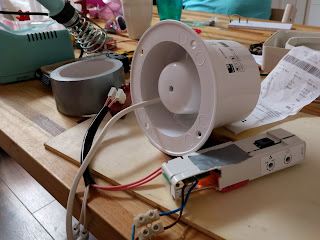
It works! Note the piece of paper lifted by the air flow, the new orange capacitor peeking through, and the flange still being attached to the new fan.
It works! Note the piece of paper lifted by the air flow, the new orange
capacitor peeking through, and the flange still being attached to the new fan.
Finale

First step was to remove the old fan from the ventilator housing and change the wiring a bit. While messing with the circuit I had removed the original connectors since they seemed flaky, so everything is now either soldered or attached with screw terminals.

The fan attached to the (upside-down) chimney top. Note the two bolts that just allow the fan to turn.
The fan attached to the (upside-down) chimney top.
Note the two bolts that just allow the fan to turn.
Next step was installing the new fan. In principle the new fan just fitted in the top part of the chimney, except that it had a flange. While very useful for the scenario where I would do what the installation instructions say, I was not planning to do that. Fortunately a plastic flange is no match for me and my hacksaw.

I then drilled two holes through the chimney top and the pipe around the fan, while taking care not to get in the way of the fan blades. Through the holes went two flat head bolts, and on the bolts went two nuts that I secured with a tiny drip of super glue. The top actually has an inner and an outer pipe. The inner one goes inside the chimney, while the outer sits on the outside. The fan is bolted to the inner pipe. The heads of the bolts were flat enough not to stop the top to go inside the chimney pipe. So I ran the wire through the chimney, put the top back on the roof, and went downstairs into the bathroom to hook things up.

Inside, things were straightforward in concept. But trying to get a bunch of wires to fit under the cover, the cover to be against the ceiling, 4 screws to through 4 holes, and somehow have a hand left over to fasten the screws above my head was somewhat tricky to say the least. And of course I had to repeat the exercise because I found I had to tweak the two potmeters a bit after the first test run.

But all is well that ends well. The ventilator works again, and is noticeably more quiet than before. However, in the future I might still add a switch so my wife can enjoy her bath in absolute silence if she is so inclined.

Some more photos


The orignal (non-working) fan. The brown part in the front-right is a bi-metal actuator to open the flaps.


Good cap.
Good cap.

Bad cap.
Bad cap.


Removed the original fan. Note the feed-through for the  new fan's wire fixed in place with some hot glue.
Removed the original fan. Note the feed-through for the
new fan's wire fixed in place with some hot glue.

The new fan in the upside-down chimney top. The wire will run through the chimney pipe and connect to the controller in the orignal casing.
The new fan in the upside-down chimney top. The wire will run
through the chimney pipe and connect to the controller in the orignal casing.


The chimney top back where it belongs. Nothing to see here, folks!