Showing posts with label AVR. Show all posts

Tuesday, 25 April 2017

Lab power supply

My new power supply.

For quite some time I have been wanting an adjustable power supply. Both for convenience and hacker credits. Unfortunately, a really good one with all the goodies that I would like to have (multiple outputs, measurements, current limiting, computer control) is somewhere in the €4-to-500 range, which I find a bit too much.

But I still want my fancy power supply!! So I started thinking about making my own. Unfortunately I have no real experience with designing these things. Because of that it seemed a good idea to start with building some kind of kit. This would give me some experience, and possibly give me something to tinker with to see what works and what not.

After some browsing on the Internet I found this kit. It had favourable reviews, and a nice set of features: 0-28V, 0.01-2A, current limiting, short circuit protection,  digital display, current and voltage measurements, all for less than €20!

Of course, I needed to add some other stuff to make it a fully working PSU. A case, heat-sink, fan and banana plug terminals I found on eBay, and a mains switch, mains connector, knobs and a toroidal transformer I bought on-line.  A fuse holder, stand-offs and miscellaneous bits of wire and fasteners came from the well-known pile-of-stuff-that-I-might-need-in-the-future.

Assembling the actual kit was the most straightforward part of the exercise. All parts where there, all through-hole, so no worries at all. The design consists of two boards: an analog board that contains the rectifier, filters and power transistor, and a digital board that has an ATMEGA8, LCD, and two rotary encoders. A ribbon cable connects the two boards, and carries power, two voltage signals coming from the analog board that represent the output current and voltage, and one voltage signal going into the other direction that controls the power transistor. All regulation is done in software, so the ATMEGA monitors the output voltage and current, and adjusts the signal to the power transistor to maintain the correct output. The concept seems very similar to this.

The more involved part of the built actually was the mechanics. Getting a proper case for it, making the right holes in the case, and finding a way to mount everything safely and securely inside. The first case I bought turned out to be a bit too small, so I had to order a new one. As it turned out, that one was actually the same model as in the pictures of the seller of the kit.
First attempt at mounting stuff. In the end I added some stand-offs to the fuse-holder, so it no longer sits directly against the back panel. And I put a bit of anti-slip netting for the transformer to help it to stay put.

For mounting I tried to limit the number of holes in case, for looks, but also very much because any metal parts sticking through the case could potentially carry a large potential in the electrical sense. So I glued some stand-offs behind the front panel of the case to attach the digital board and display. To fix the transformer to the case, I stuck a metal bolt through the plastic lid (of a peanut butter jar), and glued that to the bottom. For glue I used two-component epoxy, which seemed to work reasonably well on the materials involved.

On the back of the case I added a mains connector, and a fuse holder on the inside. The fuse itself caused me some problems. I initially figured that a ~200mA slow fuse should be sufficient. Unfortunately, even 500mA fuses kept blowing during power-up, most likely because the large filter capacitor draws quite some current initially when charging. At the moment, I am using a 1A fuse, which should be good enough to prevent fire, but might not be good enough to prevent the transformer from getting damaged if ever the electronics fail catastrophically.
Everything on the inside. The digital board sits in front, the analog board on the left side, and the transformer on the right.The fan on the heat-sink is triggered by a temperature sensor, and draws air through in the bottom of the case. 

The power supply is able to deliver up to 2A at up to 28V, and can be used in voltage limiting or current limiting mode. It constantly shows the set maximum voltage and current, and what is currently actually delivered. The two rotary knobs change the voltage and current set-points, and pressing a knob stores the set-point as a default. The fan occasionally switches on (triggered by a temperature sensor on the heat-sink), but at least during my typical usage it is hardly ever  needed. So far I am very happy with the power supply. It is especially convenient to be able to see the output current when powering something.

As the ATMEGA8 had two unused pins, it should be possible, in principle, to add a serial interface for controlling it from a computer. This would involve moving some signals around to free up the UART pins, but that is hardly a problem.  Other things on my wish list would be a output enable/disable switch, a mode where the supply switches off when exceeding the current or voltage set-point, and set/used power  (in Watts) on the display, next to current and voltage. I think most of this could be implemented in software, but I would have to start from scratch. Unfortunately, the AVR came already programmed, and the flash memory was locked, so I could not download the software for hacking. I decided to leave these possible improvements for another day,

Anyhow, at the moment I am more than happy enough with the supply as it is. So for now I will spent my time on other projects.


Another view from the top.

Wednesday, 4 January 2017

Children's countdown timer

Occasionally, our children need some help with the concept of time. According to them, some of those minutes are much shorter than others (think watching TV vs. driving to the Efteling). To help them with this, I have been promising to make something for the past half year. But now it is ready!

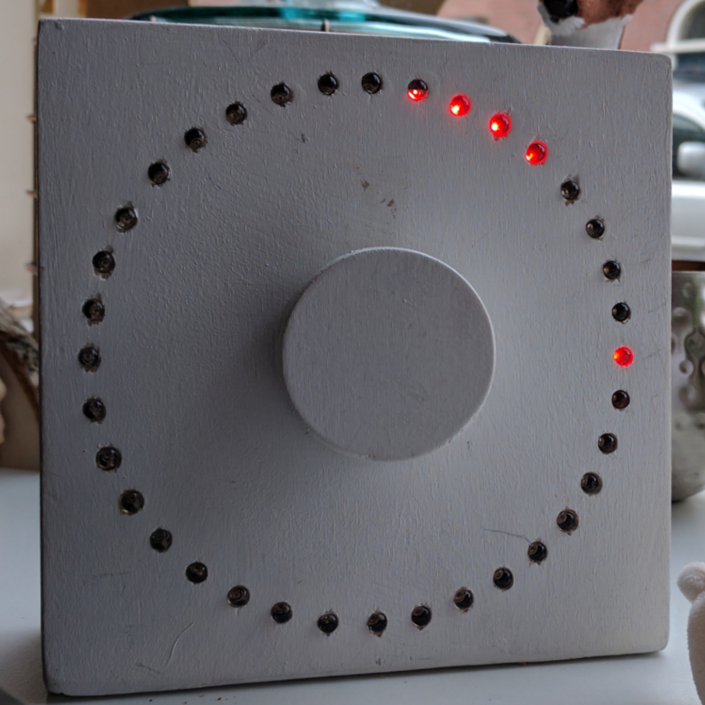
After spending about two days on it over a period of six months, here is the result: a children's countdown timer. It shows clearly how much time is left for a certain activity, and also plays a tune when time is up.

The children's timer. Unfortunately, the multiplexing of the leds combines unfavourably with the shutter of the camera. To the naked eye, all leds in the upper-right quadrant are lit.

By turning the knob clockwise, more and more of the leds along the ring are switched on. After not moving the knob for 5 seconds, the timer starts counting down. One after another, the leds slowly decrease in intensity and switch off. Each led takes 100 seconds, so the full circle uses a full hour. When all leds are off, time is up and a song is played on a piezo buzzer while the leds show a flashy pattern. By turning the knob clockwise past "zero", it is possible to switch between silent mode and audible alarm (non-silent) mode. In non-silent mode, the buzzer also clicks when turning the knob, providing feedback on whether an audible alarm is enabled.

Under the hood

The main parts of the timer are 36 red leds, two 1.5V AA batteries, a 3.3V step-up converter from the parts bin (Sparkfun NCP1400-based), a rotary encoder (from conrad.nl), a piezo buzzer that came with an old computer mainboard, and an Atmel ATtiny2313 for a brain.
A look under the hood. The piezo buzzer, the step-up converter and the AVR are approximately on a straight line from the bottom-left to the centre. All leds are on, and the batteries deliver a current of 6.3mA.
The 36 leds are driven as 3 sets of 12 via charlieplexing, using 12 microcontroller pins. This arrangement uses more pins than multiplexing the leds in a single set, but it allows three leds to be lit at the same time, increasing the average brightness using less current. Without going into details, this has to do with the non-linear response of led vs. current.

Since debugging this kind of setup is very hard, I tried to keep the software as simple as possible. A single "master" timer fires an interrupt 2600 times per second. The main purpose of this is to refresh the "display". The correct leds are switched on or off according to what needs displaying. Four levels of intensity per led, 12 leds, and 2600 interrupts per second lead to a refresh frequency of 55 Hz, which shows no flicker (to the naked eye at least ;-)).


A look at the back side of the board. The other side can be so clean because this one is a bit of a mess.
After updating the display, the routine samples the two input pins connected to the rotary encoder. By filtering over 16 samples, the signals are debounced to get a reliable input. And finally, a software counter divides the master clock to generate a timer "tick" at 5 Hz to be used by the rest of the software for time-keeping.

Events for timer "ticks" and changes of the rotary encoder are communicated to the rest of the software using bit flags. After every interrupt, the main software loop wakes up, and if there is an event, this is handled in the loop.

To play music, a separate timer is connected to the piezo speaker, that generates the notes. The music is stored encoded in the flash image and played at a pace determined by the "tick" events ultimately derived from the master timer.

When the countdown timer is switched off, the oscillators of the microcontroller are disabled and the ATtiny enters a deep sleep mode. Just before this happens, one of the inputs connected to the rotary encoder is set-up such that it will wake up the microcontroller when the signal changes. If the rotary encoder is in a position where one of its inputs bounces between on and off, this could prevent the microcontroller from entering deep sleep. To counter this, the input that wakes the micro is alternated between the two inputs every time sleep mode is enabled. So if the AVR wakes up due to a bouncing pin, it will time out since there is no actual input after the debouncing filter. It then switches to the non-bouncing pin, and enters sleep mode again.

The software is written in C using avr-libc, and compiled by avr-gcc. The current version takes 1748 bytes of flash memory, leaving exactly 300 bytes for possible extensions. The circuit has a header that is compatible with an USBasp to allow in-circuit updating of the software, something that has already proved very useful. Since the circuit normally runs at 3.3V, but the USBasp needs 5V, it is necessary to disconnect the battery before programming, and power the circuit from the programmer itself. In hindsight, I should have added a jumper to make this more convenient and less error-prone, but so far I remembered to remove the batteries when needed.

I put the software on https://github.com/bart-h/avr-timer for those that are curious.

Power usage

Because the contraption runs of a battery, power usage is an important consideration. When switched off, the system itself draws an idle current of 0.5μA after the step-up converter. Assuming a battery capacity of 1Ah, this would correspond to a battery-life of 228 years! Or actually, it means that other things will dominate the battery drain. Before the step-up converter, about 12μA is used, mainly by the converter itself. Initially I was irked to fix this 4% efficiency problem, but then I realised that the battery life would still be 9.5 years. Close enough to infinity for my purposes.  And when the system is fully active, the efficiency increases to about 90%.

When the countdown timer is running and all leds are switched on, the system draws 6.3mA at the battery. Running a countdown of a full hour (starting with all leds on, and ending with all leds off) then uses 3.15mAh. Again assuming a 1Ah battery capacity, this would allow 317 runs, more or less one per day for a full year.

The largest power drain is by the buzzer and its series resistor. When it is driven high, it draws ~30mA. Fortunately, when playing notes, the buzzer is switched on and off constantly, as sound is made by voltage changes, not stable levels. This already halves the average current. In addition, the music contains pauses that set the buzzer to 0V. Because I do not have an integrating power meter, I do not know how much power is actually used when playing music. But because the tune takes no more than 20 seconds, I assume the power usage can be neglected in the overall scheme of things. While turning the knob, the buzzer also toggles to make clicking sounds. Here I took care to switch the buzzer level back to 0V as soon as possible, to conserve power.

Because an real Alkaline AA battery actually has a capacity closer to 2Ah, all calculated lifetime numbers should be doubled as well in reality. But the final proof will be when I have to replace the batteries...


The timer running when it is dark. Because the camera uses a much larger exposure time, all leds that are lit also appear on in the picture.