Sunday 10 November 2019

Upgrading an Eee PC 901


Our oldest daughter has many dreams. One of them is to make computer games. Being a techie myself, I feel I have to encourage such dreams. As a start I bought her a book to learn to program in Python. But to do this she needs access to a computer as well. As it happens I still own an old ASUS Eee PC 901 netbook. To me it is no longer very useful, but it would be perfect for my daughter.

So I took a good look at the machine. The keyboard and screen were still good. The battery was good enough, but one trackpad button was broken. And even when running Lubuntu it felt very slow. To make her first "own" computer experience a good one, I figured I should try to improve it. So I decided to fix the trackpad button, and invest about €20 on upgrades. Given the age of the netbook, it did not make sense to spent more on it.

An easy upgrade was maxing out the ram by replacing the 1 Gb DIMM by a 2 Gb one (8 euro delivered).

Performance of the built-in SSD. Note that this is the 4GB one. Its 8GB sibbling is even slower.
The next bottleneck of the system was the 12GB of flash storage, in the shape of a 4GB and a 8GB module. From what I could gather, this was implemented as some kind of compact flash internals on an PCI-express form-factor, via a PATA bus. Note that the PCI-express form-factor means that it is mechanically like PCI-express, but NOT electrically. All in all, this made for a very slow pair of SSDs that were also expensive to extend or replace.

Fortunately, the SSD connector also had a SATA interface hiding on it. And I already had bought a little PCB to break this out many years before, when I was still planning to use the system myself. So I went to AliExpress, and bought a cheap (13 euro shipped!) Netac 60Gb SSD. To make it fit in the system, I had to remove the case of the SSD and the SATA connector. This meant I had to solder the whole thing directly to the break-out PCB, but that was only a minor problem.

SSD soldered onto the break-out PCB.


Break-out PCB with SSD connected to the mainboard. Unfortunately, there was no 5V on the break-out PCB, so I had to take that from somewhere else.


To make this work even better, I flashed a new "3rd party" BIOS that enabled the AHCI SATA interface, as the stock BIOS only allowed the IDE compatibility mode. Unfortunately, this still did not allow me to boot from the SATA SSD, so I had to keep one original flash module to boot from. But as this is really only used to load the linux kernel and initramfs, that has very limited impact on performance.
New SSD is recognized by the BIOS!
Nice speed improvement!
Apart from the above, I also had to do two small repairs: one was to replace one of the above-mentioned buttons of the trackpad, as that was not working well anymore. The other was to bodge my SATA break-out PCB, as I managed to damage it when I tried to remove a connector.
Bodge needed because I damaged the tracks.


Another bodge to connect the replacement trackpad button.
Anyway, after these improvements, this system has another couple of years left in useful life!


22-6-2020: fixed spelling mistake.

Using the AVR USI to create a I2C peripheral device

As part of a more complex project, I recently felt the need to implement an I2C peripheral on an ATtiny2313, using its Universal Serial Interface ("USI"). As described in the link, the I2C protocol allows multiple devices to communicate using only two signalling wires.

In case you want to do something similar, here are a few suggestions that helped me a lot:
First of all, make sure that you can see what is going on. The main tools I used for creating and debugging were my DS1054 oscilloscope to look at the various signals, a Bus Pirate that can act as an I2C controller, and an USB-to-serial convertor connected to the AVR UART so that I could watch debug-messages.

And secondly, while I am generally very impressed with the quality of the AVR datasheets, the USI part was described a bit too loose for me to understand exactly what behaviour the various register settings would cause. So after some frustrating attempts, I started to dump the various USI-related registers over my serial debug output, to see what exactly happened. This helped to clarify some points, so I get my I2C peripheral to work.

Now to continue with the main story...

As said, the I2C protocol uses 2 signal-lines: SCL and SDA, being the clock and data line, respectively. Both of these are normally pulled high externally, and the devices on the bus pull them low (to ground) to communicate. Typically, the bus has one  controller device and one or more peripheral devices, but multiple controllers are possible as well.

During normal communications, SDA may only change when SCL is low. The two exceptions are the "start" and "stop" conditions. (The latter is only really important for controller devices, so I will not discuss it here.) Another important aspect of the protocol is that the controller controls the SCL line, but after the controller pulls the SCL low, peripheral devices are allowed to keep it low to slow things down in case they cannot keep up.


I2C protocol in a nutshell. Shown are the start condition ("S"), data transfer ("Bx") and stop condition ("P"). Original drawing by  Marcin Floryan and taken from wikipedia.


The "start condition" signal pulls SDA down when SCL is high. This acts as sort of a bus-reset, and makes all peripheral devices pay attention to what is coming next. Next step after pulling SDA down is that the controller also pulls the SCL down, to prepare for the first data-bit (remember that SDA normally only changes if SCL is low). Luckily, the AVR's USI helps us here. It can generate an interrupt when the SDA line goes low while SCL is high, and after the controller then pulls SCL low, the USI will keep it low until we tell it otherwise. This makes sure that even our slow code and a very fast controller will be in sync at a certain moment.

After the start condition, the controller will proceed by sending a string of 7 address bits, and 1 R/W (read-write) bit. The address bits identify for which peripheral the rest of the message is meant, and the R/W bit tells whether the controller expects to send or receive data. To read these 8 bits, we could simply setup the USI to sample a bit of SDA each time that SCL goes from low to high, do that for 8 bits, and then interrupt. But the way the USI works is that it counts in terms of SCL flanks (both low-to-high transitions, when a bit is sampled, and high-to-low transitions, that I will come to later), so we need 16 of those. Since high-to-low changes are counted as well, things get slightly more complicated, as explained below.

When serving the "start" interrupt, SCL might not have gone down yet, so we need to synchronise somewhere. All code I could find simple used a busy-loop to wait until the SCL went down. But busy-loops in interrupt routines is never a really good idea, especially when waiting for some external signal that is not under our control. So I did something more elegant: when the SCL line was still up, I set the USI to wait for one additional flank. Using the fact that the USI will keep the SCL low until released, and doing things in the right order, I could make this safe for race conditions. Unfortunately, the USI can only count a maximum of 16 flanks, and this scheme would need up to 17. So the next trick is to only sample the first 7 address bits, and count either 14 or 15 flanks.

ISR(USI_START_vect,ISR_BLOCK)
{
  /* Start condition.
   * Controller might still have to clock up at this point
   * Once it goes down, USI will keep it down, as long as we did not clear 
   * the start condition.
   */

  /* make sure that sda is in the right mode, as a start condition can happen
   * virtually anytime.
   */
  set_sda_input();
  set_sda_high();
  
  /* Next will be the 7 address bits (14 flanks on clock) */

  /* To prepare for the next step after receiving address, we need to "output"
   * 1s, so put those in the DR.
   */
  USIDR = 0xff;
  
  /* Assume clock is still high, so we prepare for 15 flanks, and fix it later. */
  set_status_register(0,1,15);

  /* Enable full mode */
  set_control_register(1,1,1);

  /* Setup for receiving address */
  i2c_peri_state = I2C_ADDRESS;

  /* Check if clock is down */
  if ((I2C_PIN & _BV(I2C_CLK))==0) {
    /* Line went down already, so only 14 flanks are needed now. 
     * Doing check like this will prevent racing.
     */
    /* Set 14 flanks.
     */
    set_status_register(0,1,14);
  }
  release_start_condition();
}
The code above shows how the "start" condition interrupt routine is done. Note that the release_start_condition() call is from where on the USI will no longer keep the SCL low after the controller pulled it down. More code and details can be found on my github.

Once the 7 address bits are received, we can check if we are the peripheral that is being addressed. If not, we can simply go off the bus, and wait for the next "start condition" signal. But if the address is correct, we need to get the R/W bit, and after that acknowledge our reception to the controller. In general, acknowledgement is done by the receiver after every 8 bits, by pulling SDA down for the 9th bit. As we already know that we should acknowledge, we can setup the USI to receive one more bit,  then pull SDA low (output a 0), for one more SCL cycle, and then interrupt again. By smartly combining the R/W bit and the acknowledge bit in 4 SCL flanks, we do this part with only three interrupts (start condition, first 7 bits, R/W bit and acknowledge). This is the same number of interrupts that other implementations use, because these need to handle the acknowledge bit separately as well.
/*
 * Overflow function: (some) data was transferred.
 */
ISR(USI_OVERFLOW_vect,ISR_BLOCK)
{
  uint8_t data;
  
  data = USIDR;
  if (i2c_peri_state & I2C_WAIT_ACK1) {
    /* We send a byte. Now try to get an acknowledge. */
    if (i2c_peri_state & I2C_WAIT_ACK2) {
      i2c_peri_state &= ~I2C_WAIT_ACK2;
      set_sda_input();
      set_status_register( 0, 1, 2 );
      goto go_leave;
    } else {
      /* check if the controller acked */
      if (data & 1) {
         /* NACK */
         goto go_idle;
      } else {
         i2c_peri_state &= ~I2C_WAIT_ACK;
         set_sda_output();
      }
    }
  } else if (i2c_peri_state & I2C_ACK_RECEIVE) {
    /* Done acknowledging our reception */
    i2c_peri_state &= ~I2C_ACK_RECEIVE;
    if (i2c_peri_state == I2C_IDLE) {
      goto go_idle;
    }
    /* release sda and set to input */
    set_sda_high();
    set_sda_input();
    /* wait for 16 flanks */
    set_status_register( 0, 1, 16 );
    goto go_leave;
  }
  
  switch( i2c_peri_state ) {
  case I2C_ADDRESS:
    /* First 7 address bits are received. */
    if (data==(0x80|(I2C_PERI_ADDR>>1))) {
      /* The address, now get our send-receive bit */
      i2c_peri_state = I2C_READ_WRITE;
      /* As this is our address, we can have the hardware do the acknowledge. */

      /* Enable output. 
       * This is okay, as the start ISR made sure that we are outputing "1", i.e. nothing.
       */
      set_sda_output();
      /* Clock is down. 
       * Next clock up will shift RW bit into DR0, and 0 to DR7
       * Next clock down will latch DR7 into SDA. -> ACK
       * Next clock up will shift our 0 into DR0, and 1 out to DR7
       * Next clock down will latch DR7 into SDA, i.e. release SDA again.
       */
      USIDR = 0xbf;
      /* Wait for 4 flanks. */
      set_status_register( 0, 1, 4 );
      goto go_leave;
    }
    /* not us, get off the bus */
    goto go_idle;
    break;
  case I2C_READ_WRITE:
    /* This is the tail end of the address phase.
     * Only the RW bit was still needed, and the ACK was
     * already dealt with by the hardware.
     */
    /* RW bit is the second bit */
    if (data&2) {
      /* controller requests data */
      i2c_peri_state = I2C_SEND_1;
      // we are ready to send now
      goto go_send;
    } else {
      /* controller will send more */
      set_sda_input();
      i2c_peri_state = I2C_CONTROL;
      /* prepare to receive 8 bits */
      set_status_register(0,1,16);
      goto go_leave;
      return;
    }
    break;
  case I2C_CONTROL:
    /* get our control value */
    i2c_peri_cmd = data;
    switch(data) {
    case 0x01: /* set pwm colors */
      i2c_peri_state = I2C_RECEIVE_6;
      goto go_ack_receive;
      break;
    case 0x10: /* read voltage */
      i2c_peri_state = I2C_IDLE;
      event_trigger( EVENT_I2C_PERI_CMD );
      goto go_ack_receive;
      break;
    case 0x20: /* read string */
      i2c_peri_send_buffer[0] = 0xde;
      i2c_peri_send_buffer[1] = 0xad;
      i2c_peri_send_buffer[2] = 0xbe;
      i2c_peri_send_buffer[3] = 0xef;
      i2c_peri_send_buffer[4] = 0xcc;
      i2c_peri_send_buffer[5] = 0xaa;
      goto go_ack_receive;
    default:
      goto go_idle;
    }
    break;
  case I2C_RECEIVE_1 ... I2C_RECEIVE_6:
    i2c_peri_receive_buffer[ i2c_peri_state - I2C_RECEIVE_1 ] = data;
    if (i2c_peri_masterstate == I2C_RECEIVE_1) {
      /* got all our bytes */
      event_trigger( EVENT_I2C_PERI_CMD );
      i2c_peri_state = I2C_IDLE;
    } else {
      --i2c_peri_state;
    }
    goto go_ack_receive;
    break;
  case I2C_SEND_1 ... I2C_SEND_MAX:
  go_send:
    // here we start sending...
    
    USIDR = i2c_peri_send_buffer[ i2c_peri_state - I2C_SEND_1 ];
    set_status_register( 0, 1, 16 );

    if (i2c_peri_state == sizeof(i2c_peri_send_buffer) ) {
      i2c_peri_state = I2C_IDLE; /* wait for ack, and go idle */
    } else {
      ++i2c_peri_state;
    }
    /* Setup so we wait for an ACK afterwards */
    i2c_peri_state |= I2C_WAIT_ACK;
    goto go_leave;
    break;
    
  case I2C_IDLE:
  default:
    goto go_idle;
  }

 go_idle:
  i2c_peri_go_idle();
 go_leave:
  return;

 go_ack_receive:
  /* we need to acknowledge our receiving... */
  i2c_peri_state |= I2C_ACK_RECEIVE;

  /* clock is down --> bring sda down to ack*/
  set_sda_output();
  set_sda_low();
  /* interrupt after two flanks */
  set_status_register( 0, 1, 2 );
  return;
}
The code above shows the "overflow" interrupt routine, that is called when a certain number of flanks is received. It handles everything from receiving and checking the address bits, receiving and sending further data, and sending, receiving and checking acknowledge bits.

For sending data, we need to switch the SDA pin to an output, send 8 bits, interrupt, switch SDA to input, receive one bit (acknowledge by the controller), interrupt again and check the acknowledge bit. If the acknowledge is ok, we can then send the next 8 bits, if needed. The USI hardware is configured such that a bit is output to SDA when SCL goes from high to low, so it is in the opposite phase as receiving a bit. This allows combined reading and writing: writing a 1 simply means that the USI does not pull the SDA low. But if another device on the bus does pull SDA low, the next flank will read a 0 (low) signal. This is the trick I used to combine reading the R/W bit with acknowledging in one go. Note that the USI only uses a single 8-bit shift register. Every SCL cycle, the MSB is shifted out to SDA on one flank, and SDA is shifted into the LSB on the next flank.

I believe the code above is a nice example of how to make an I2C peripheral using an AVR USI, and I hope this was useful or even interesting for you as well.

2020-6-20: updated to remove slavery references.

Sunday 3 November 2019

Magic Wand: Charlieplexing LEDs

Introduction

My daughter wanted to be a witch for Halloween. For that costume was of course a Magic Wand a mandatory accessory.

The finished Magic Wand
I try to give some information about how I have made this toy in this blog post.
I have made a movie to show the different patterns, but I noticed that the sound was not correct. This will be reuploaded at a later time.

 There is a debug interface to upload new firmware to the magic wand.

Mechanical construction

The following picture shows the main items I have used to make the magic wand: 
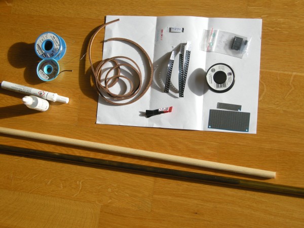
  • As base I have used a 12mm diameter wooden stick.
  • To store the electronics and batteries I have used a brass tube with an inner diameter of about the same as the outer diameter of the wood. With a bit Kapton tape is the stick stuck in the tube. This part forms the handle of the magic wand. It is also possible to use an empty tube like part such as a (whiteboard) marker.
  • A leather cord is glued to the handle to make it feel and look nice.
  • LEDs are glued with super glue to the wood before soldering the wire to each LED.  I have used 0603 for the body of the wand and 0805 for the top.  In my case I have used the colour purple for all led.
  • The electronics consist of mainly a Attiny84 with some resistors and capacitors.  
  • The chip is soldered on a piece of SMD prototype board. This has a bit of a special grid and was not perfect in that aspect but it was very thin and could be easily cut to size and fixed in the wood & tube.  I have used this.
  • The LED and electronics are connected with a 0.2mm diameter isolated copper wire. The isolation layer is burned off on the locations where I wanted to solder.
  • Paint and lacquer to colour the stick. I have used acrylic paint.
  • Furthermore is solder, flux and solder wick needed.
I have a few tips on the assembly:
  • It is difficult to get the stick in the right shape.  Clamping the stick in a drill and run it over sanding paper did not work so well.  Cutting it with plane in the right shape and sanding afterwards did work for me.  A small lathe is probably nice for this kind of round work pieces.
  • The super glue worked very well to tack the led to the wood and to solder it. A bit heat is needed to remove the glue from the led on the points where it should be soldered. But no led came of during the soldering.
  • With the solder iron on 450C is the isolation material on the copper wire quickly gone. This works better than a mechanical method (sanding paper, knife etc.) however is not good for the tip of the soldering iron.
  • I have painted clear lacquer over the LEDs after the soldering; this to protect the led and the wires. A disadvantage of this is that the light travels side ways over the magic wand. 
  • I have put first the 8 wires on the stick with tape and then put the LEDs in between and have solder them by pulling the wire to the LED.  Probably it is easier to put lines on the stick to determine the LED position, glue the led and then pull the wires from LED to led. I expect that that works better to keep things nicely oriented. 

Electrical schematic


The electrical schematic is fairly simple. PortA of the Attiny84 microcontroller is used to drive the leds.  In principle is it possible to charlieplex in this way 56 leds (N^2-N). For this design I am using only 24 leds.  The 150ohm resistors is calculated based on a 2.8V voltage drop over the led and a 5mA drive current. In the software is never more then 1 led on at the same time so this construction is from the current load on the microcontroller fairly uncritical.
Electrical schematic of the Magic Wand
The the size of the LEDs on the body of the stick are 0603 and on the top is 0805 used.
The programming interface is working correctly when the LEDs are attached.  This does give some additional light effects when the microcontroller is programmed.
The push button is directly between the batteries and the processor board.  For testing I have used 3 AAA penlight batteries. I have used 3 stacked LR44 batteries to fit in the handle during "normal" usage.  The electrical contact points of the battery are made with thumb-tacks, which works surprisingly well.  The diode D1 protects the circuit when I forget what the + and - side of the battery should be.

With some work the electronics looks like this:
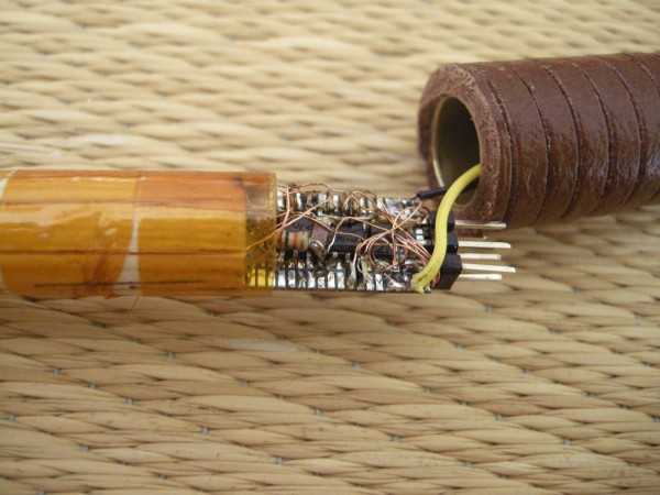
The electronics inside the magic wand.
The black wire is the (-) of the battery and the yellow the (+). The 6pin AVR ISP connector is clearly visible. The 0.2mm diameter copper wires are thin compared with the other parts.

I had to use a microscope to solder this successfully.

Software 

The firmware for the magic wand is fairly simple and written in the Arduino platform.  There is no real reason to do this; this could be done just as simple without Arduino and with a normal Makefile and avr-gcc.

A table with DDRA and PORTA values is used to address each LED correctly and to compensate for "errors" in the soldering.  By using the index in the table is each LED addressable.

The push button is connected to the power supply of the Attiny84. This means that when the button is pushed the processor gets power and comes out of the reset.  As first step is the previous animation number read out of the EEprom.
Then is the next animation shown. At the end of the animation is this new number written into the EEprom.
After this is the processor put in deep sleep to save current when the button is continuously pushed.

With this setup is it possible to repeat an animation when the button is released before the animation is finished.  A new animation    will be shown when is waited until the previous animation is finished and the push button is pushed again.

Things to improve:
  • Remove the Arduino frame work.  I am not really using it and it is probably giving some timing issues.
  • I have a flicker in the first part of each animation. Just if it is run two times.  I thought it could be because the calculations done which is adding 0 for the first ring.  But removing this with and IF statement is not solving this either.
  • Some fading or different brightness levels would be nice to add to the animations.  This must be possible with a timer interrupt but I did not had enough time before Halloween to experiment with it.
The source code:
#include <EEPROM.h>   // Items for the EEPROM
#include <avr/sleep.h>    // Sleep Modes
#include <avr/power.h>    // Power management

#define ATTINY84
#define MAXEFFECT 7
#define EEADDRESS 5

#define SLOWCYCLE 200
#define FASTCYCLE 100
#define NULLCYCLE 0

#define SLOWDELAY 400
#define FASTDELAY 200
#define NULLDELAY 3

const uint8_t dirlist[] PROGMEM  ={ B0, 
                  B00000110, B00011000, B01100000, B10000001, B00000011, B00001100, B00110000, B11000000,
                  B00000110, B00011000, B01100000, B10000001, B00000011, B00001100, B00110000, B11000000,
                  B00000101, B00010100, B01010000, B01000001, B00000101, B00010100, B01010000, B01000001 };
const  uint8_t outlist[] PROGMEM  ={ B0, 
                  B00000100, B00010000, B01000000, B00000001, B00000010, B00001000, B00100000, B10000000,
                  B00000010, B00001000, B00100000, B10000000, B00000001, B00000100, B00010000, B01000000,
                  B00000100, B00010000, B01000000, B00000001, B00000001, B00000100, B00010000, B01000000};

struct MyUseCntStruct {
   byte pattern;
   int usecnt;
};

MyUseCntStruct MyUseCnt;

void setup() {
  // put your setup code here, to run once:
   SetLed(0);
   EEPROM.get(EEADDRESS, MyUseCnt);
   MyUseCnt.pattern +=1;
   if (MyUseCnt.pattern > MAXEFFECT) MyUseCnt.pattern=0;  
}

void loop() {
  // put your main code here, to run repeatedly:
  switch (MyUseCnt.pattern) {
    case 0: 
       PatternDot();
       break;
    case 1:
       PatternRing();
       break;
    case 2:
        AllOn();
        break;
    case 3:
        TestRing();
        break;
    case 4:
        PatternLine1();
        break;
    case 5:
        PatternLine2();
        break;
    case 6:
        PatternRandom();
        break;
    case 7:
        PatternRing2();
        break;    
    default:
       PatternDot();
       break;
    }
 MyHalt();
}

void SetLed(uint8_t lednum) {
  PORTA=0; // Set all to zero before changing the led
  DDRA=pgm_read_byte_near(dirlist + lednum);
  PORTA=pgm_read_byte_near(outlist + lednum);
}

void MyHalt() {
  // function to stop the anymation and to put the processor to sleep
  SetLed(0);
  set_sleep_mode(SLEEP_MODE_PWR_DOWN);
  MyUseCnt.usecnt+=1;
  EEPROM.put(EEADDRESS, MyUseCnt);
  // now sleep
  ADCSRA = 0;            // ADC ausschalten
  power_all_disable (); 
  sleep_enable();
  sleep_cpu();             // µC schläft     
}

void RingLed(uint8_t ring, uint16_t cycle, uint16_t wait) {
  // Make a ring light
  // 0 is the ring closed to the handle and 5 is the ring at the tip.
  if (ring == 0) {
    for (uint16_t i = 0; i <= cycle; i++) {
       SetLed(1 );
       delay(wait);
       SetLed(2 );
       delay(wait);
       SetLed(3 );
       delay(wait);
       SetLed(4);
       delay(wait);
    }    
  } else {
    ring *= 4;
    for (uint16_t i = 0; i <= cycle; i++) {
       SetLed(1 + ring );
       delay(wait);
       SetLed(2 + ring );
       delay(wait);
       SetLed(3 + ring );
       delay(wait);
       SetLed(4 + ring );
       delay(wait);
    }
  }
}

void ColumLed(uint8_t column, uint16_t cycle, uint16_t wait) {
  // Make a column on the stick
  if (column ==0 ) {
      for (uint16_t i = 0; i <= cycle; i++) {
         SetLed(1);
         delay(wait);
         SetLed(5);
         delay(wait);
         SetLed(9);
         delay(wait);
         SetLed(13);
         delay(wait);
         SetLed(17);
         delay(wait);
         SetLed(21);
         delay(wait);
      }
  } else {
    for (uint16_t i = 0; i <= cycle; i++) {
       SetLed(1 + column );
       delay(wait);
       SetLed(5 + column );
       delay(wait);
       SetLed(9 + column );
       delay(wait);
       SetLed(13 + column );
       delay(wait);
       SetLed(17 + column );
       delay(wait);
       SetLed(21 + column );
       delay(wait);
    }
  }
}

void PatternDot () {
  RingLed(0,NULLCYCLE,FASTDELAY);
  RingLed(1,NULLCYCLE,FASTDELAY);
  RingLed(2,NULLCYCLE,FASTDELAY);
  RingLed(3,NULLCYCLE,FASTDELAY);
  RingLed(4,NULLCYCLE,FASTDELAY);
  RingLed(5,NULLCYCLE,FASTDELAY);
  RingLed(5,SLOWCYCLE,NULLDELAY);
}

void PatternRing() {
  RingLed(0,FASTCYCLE,NULLDELAY);
  RingLed(1,FASTCYCLE,NULLDELAY);
  RingLed(2,FASTCYCLE,NULLDELAY);
  RingLed(3,FASTCYCLE,NULLDELAY);
  RingLed(4,FASTCYCLE,NULLDELAY);
  RingLed(5,SLOWCYCLE,NULLDELAY);
}

void PatternRing2() {
  RingLed(0,FASTCYCLE,NULLDELAY);
  RingLed(1,FASTCYCLE/2,NULLDELAY);
  RingLed(2,FASTCYCLE/3,NULLDELAY);
  RingLed(3,FASTCYCLE/4,NULLDELAY);
  RingLed(4,FASTCYCLE/5,NULLDELAY);
  RingLed(5,SLOWCYCLE,NULLDELAY);
}
  
void TestRing() {
  RingLed(5, SLOWCYCLE,NULLDELAY);
}

void AllOn() {
  for (uint16_t i = 0; i <= FASTCYCLE; i++) {
    RingLed(0, NULLCYCLE,NULLDELAY);
    RingLed(1, NULLCYCLE,NULLDELAY);
    RingLed(2, NULLCYCLE,NULLDELAY);
    RingLed(3, NULLCYCLE,NULLDELAY);
    RingLed(4, NULLCYCLE,NULLDELAY);
    RingLed(5, NULLCYCLE,NULLDELAY);
  }
  RingLed(5, SLOWCYCLE,NULLDELAY);
}

void PatternLine1() {
   ColumLed(0,NULLCYCLE, FASTDELAY);
   ColumLed(1,NULLCYCLE, FASTDELAY);
   ColumLed(2,NULLCYCLE, FASTDELAY);
   ColumLed(3,NULLCYCLE, FASTDELAY);
   RingLed(5, SLOWCYCLE,NULLDELAY);
}

void PatternLine2() {
   ColumLed(0,FASTCYCLE, NULLDELAY);
   ColumLed(1,FASTCYCLE, NULLDELAY);
   ColumLed(2,FASTCYCLE, NULLDELAY);
   ColumLed(3,FASTCYCLE, NULLDELAY);
   RingLed(5, SLOWCYCLE, NULLDELAY);
}

void PatternRandom() {
    SetLed(1);
    delay(FASTDELAY/2);
    SetLed(10);
    delay(FASTDELAY/2);
    SetLed(7);
    delay(FASTDELAY/2);
    SetLed(3);
    delay(FASTDELAY/2);
    SetLed(15);
    delay(FASTDELAY/2);
    SetLed(17);
    delay(FASTDELAY/2);
    SetLed(4);
    delay(FASTDELAY/2);    
    SetLed(10);
    delay(FASTDELAY/2);    
    SetLed(2);
    delay(FASTDELAY/2);
    SetLed(18);
    delay(FASTDELAY/2);    
    SetLed(9);
    delay(FASTDELAY/2);    
    SetLed(9);
    delay(FASTDELAY/2);    
    RingLed(5, SLOWCYCLE, NULLDELAY);
}

Sunday 23 June 2019

The Motorola DSP56L307EVM signal processing board

Some information to get a Motorola dsp56L307evm digital signal processing evaluation board from 2001 working on a linux computer in 2019.

The dsp56002evm (top) and dsp56l307evm (bottom)
This is a kind of a next step after getting my old dsp56002evm working under linux.

Introduction


The dsp56L307 is a 24bit (dsp) processor and can run at 150MHz. Together with the Enhanced Filter Coprocessor (efcop) it can generate 270MIPS. I will need to do some real benchmarking, but it can probably be compared with something like a STM32F407 (arm-M4 core at 168MHz) for the calculation speed.However the 24bit Harvard architecture with 3 memory spaces makes it still different and not fully comparable with an arm-M4, which is probably much better in quite some tasks..

I have bought my board from "littlediode" on ebay. While not advertised as such, it did came as the full original EVM kit in original box; that is with documentation, software, power adapter and cable.


The first challenge is to find, roughly 15 years after discontinuation and changing the company from Motorola to Freescale to NXP, all the documentation and tools back in the archives. My board did come with a CD with software like assembler and simulator, but that was not the latest version. The box did not include DSP specific test software for the board.

The wayback machine, does help a bit to find old pages, manuals(pdf) and software back. There are Motorola related pages and Freescale related pages that can be found back. It is advisable to browse a bit between the different snapshots to try to try to find what you are looking for. Another source are old university pages; this dsp was used for some courses.

 Then are all the tools that can be found only for dos / windows available, which gives inherently inconveniences for using those tools on Linux.


Most of the dos/windows tools can be used under a wine console, this shares at least the filesystem. For the dsp56002EVM was it partly needed to use dosbox / dosemu to get the debugger working, which is way more cumbersome in usage.

My current status is:
  • I can use the official (windows) tools and IDE for writing and compiling code.
  • I can use openocd to upload the code and inspect memory and registers to validate the working. (It is not real debuging, for that I would need gdb)
The next sections give a bit more information for this.

Setting up the (Windows) toolchain

The latest version of the required tools are part of the Freescale Symphony studio. This package contains the assembler, linker, c-compiler and tools to change the COFF files in a more universal format.
To get the eclipse based IDE working is it necessary to install an old  Java runtime. I was able to get one from oracle. This does need an account / login.

After installing this with "wine" then we get three sub directories in the install directory:

├── [4.0K]  dsp56720-devtools 
│   ├── [4.0K]  dist
│   │   ├── [4.0K]  dsp56720
│   │   ├── [4.0K]  gcc
│   │   │   ├── [4.0K]  bin  <-- directory with all the tools !
│   │   │   ├── [4.0K]  dsp
│   │   │   ├── [4.0K]  etc
│   │   │   └── [4.0K]  lib
│   │   ├── [4.0K]  gdb
│   │   └── [4.0K]  openocd
│   │       ├── [4.0K]  bin
│   │       └── [4.0K]  driver
│   ├── [4.0K]  doc
│   └── [4.0K]  licenses
├── [4.0K]  eclipse <-- directory with "startsymphony.bat" to start eclips based IDE
│   ├── [4.0K]  configuration
│   ├── [4.0K]  features
│   ├── [ 12K]  plugins
│   └── [4.0K]  readme
└── [4.0K]  sample-projects
    ├── [4.0K]  ASM-Tutorial
    │   └── [4.0K]  Debug
    └── [4.0K]  C-tutorial
        └── [4.0K]  Debug
The batch file to start the eclips based IDE is setting some paths which are necessary for the tool chain to work correctly.  These paths have to be set as well when we want to use the tools, for instance the gcc based c compiler, outside of the IDE. The contents of the batch file is:

~/.wine/drive_c/Symphony-Studio/eclipse$ cat startsymphony.bat 
@echo off

set DDT_HOME=C:\Symphony-Studio\dsp56720-devtools
set G563_EXEC_PREFIX=%DDT_HOME%\dist\gcc\lib\
set PATH=%DDT_HOME%\dist\gcc\bin\;%PATH%
set DSPLOC=%DDT_HOME%\dist\gcc

start C:\Symphony-Studio\eclipse\symphony-studio.exe

exit

The Symphony-studio program can also be started from the start menu. It does look to have sometimes problems to start properly; the windows stay empty. A bit clicking and loading some files seem to help.
The Symphony-studio IDE with assembler output.
With some well chosen command line options is it also possible to get the C-compiler working from the wine console.

$ wineconsole
C:\Symphony-Studio\dsp56720-devtools\dist\gcc\bin>g563c -BC:\Symphony-Studio\dsp56720-devtools\dist\gcc\lib hola.c -o hola.cld

The assembler can also be used stand-alone:

$ wineconsole
C:\Symphony-Studio\dsp56720-devtools\dist\gcc\bin>asm56300 -A -lpass.lst -B pass.asm

Setting up OpenOCD

The current OpenOCD (version 0.10.0) as some issues and is not fully supporting the dsp563xx anymore. The register structure is asking for an "exist" parameter which was missing. And the read and write functions for the memory have an incorrect word size definition. I have submitted two patches to openocd to solve this. The patches can also be found here.  Depending when this is read can this be already included in the latest openocd version.

Further more is a configuration file for openocd needed to make the jtag interface, target and board work together.  This  is still work in progress. The contents for the target is for now as follows:

$ cat dsp5gl307.cfg
if { [info exists CHIPNAME] } { 
   set _CHIPNAME $CHIPNAME
} else {
   set _CHIPNAME dsp56L307
}

if { [info exists ENDIAN] } { 
   set _ENDIAN $ENDIAN
} else {
  # this defaults to a big endian
   set _ENDIAN big
}

if { [info exists CPUTAPID] } {
   set _CPUTAPID $CPUTAPID
} else {
   set _CPUTAPID 0x0181101d
}
#jtag scan chain
jtag newtap $_CHIPNAME cpu -irlen 4 -ircapture 1 -irmask 0x03 -expected-id $_CPUTAPID
#target configuration
set _TARGETNAME $_CHIPNAME.cpu
target create $_TARGETNAME dsp563xx -endian $_ENDIAN -chain-position $_TARGETNAME
#working area at base of ram
$_TARGETNAME configure -work-area-virt 0

And for the EVM board I have made the following configuration file:
$ cat dsp56l307evm.cfg
# Script for freescale DSP56L307EVM
#
# the build in wiggler Jtag interface
source [find interface/parport.cfg]
#jtag speed
adapter_khz 100
reset_config trst_and_srst
# Some additional delays to improve the initialisation.
adapter_nsrst_delay 100
jtag_ntrst_delay   20

source dsp56l307.cfg

#setup flash 
#missing for now; did not work yet

proc enable_fast_clock {} {
    # Programm a factor of 5 into the PLL 
    # 12.288MHz * 3 = 36.8MHz
    mwwx 0xFFFFFD 0x060002
    # enable a timer to see a LED flashing
    mwwx 0xFFFF8F 0x000021
}
# initialize only board specifics - reset, clock, adapter frequency
proc init_board {} {
    global _TARGETNAME
    
    $_TARGETNAME configure -event reset-start {
        # Removed the system reset to be able to have the platform run
        reset_config trst_only
        adapter_khz 500
    }

    $_TARGETNAME configure -event reset-init {
        # this will be done only once!
        # perform a tap and system reset to be sure that the memory is cleared
        reset_config trst_and_srst
        enable_fast_clock
        adapter_khz 500
    }
}

I will upload the final version (when the flash is also working) to git for inclusion into the openocd source.

When starting and working with openocd you should get something as on the pictures below:
Starting openocd with the dsp56l307evm.cfg config file
Connecting with telnet to the debug session

The dsp653xx target of openocd uses a special parameter "memspace" in which of the 4 memory spaces the data is put:
Set memspace #
  • 1 gives access to X data memory  (MEM_X = 0)
  • 2 gives acces to Y data memory (MEM_Y = 1)
  • 3 gives access to the combined X and Y memory called L memory (MEM_L = 3).
  • all other values result in access to P memory or program memory (MEM_P = 2)
This can be used to load data in all memory spaces as follows:

> set memspace 0  # set P memory as default
> load_image program.p 0x0 s19

> set memspace 1   # set X memory as default
> load_image program.x 0x0 s19

> set memspace 2   # set Y memory as default
> load_image program.y 0x0 s19


Checking if open ocd is working by programming one of the timers:
> mwwx 0xFFFF8F 0x21
> mdwx 0xFFFF8F

To change the PLL we can do this:

> mwwx 0xFFFFFD 0x060002    <--  PLL (2+1)=3 x 12.288MHz = 36.864MHz
> mwwx 0xFFFFFD 0x060008    <--  PLL (8+1) =9 x 12.288MHz = 110.592MHz
> mwwx 0xFFFFFD 0x06000B    <--  PLL (11+1) =12 x 12.288MHz = 147.456MHz

Which makes the timer go faster as well.

SREC

The (windows) SREC tool can be used to convert the special CLD COFF files to something more universal that can be loaded by openocd to program the dsp.
This tool has to be run with the following options:
$ srec -r -t 4 infile.cld 
The two necessary options are:
  • The -r option is needed to flip the direction of the words to fix the Endianness difference between host and the dsp. 
  • With the -t 4 option are the words expanded from 24 bit to 32bit.
this image can be loaded by openocd onto a target:
> load_image infile.p 0x0 s19

This srec tool can be called from the Symphony IDE to convert the files after compiling.

Saturday 3 November 2018

Firewire audio interfaces (hardware)


After my slightly disappointing experience with the Soundblaster Audigy 2 ZS I decided to step up a bit with my "project". In the past was or maybe still is an external firewire audio interface considered the best performance. The clock for audio stream is supposedly more stable than with USB and external is there less noise than inside of computer case. Therefore are all the external devices considered semi professional and come with at least 24bit and 96kHz sample rates in combination with balanced and unbalanced signal inputs and outputs to reduce noise.

The support for Firewire devices under linux is a bit sketchy:
  1. As usual are manufactures of such devices not releasing drivers and or documentation to make (open source) drivers.
  2. From 2007 and on went firewire the way of the dodo in favorite of USB; less computers got firewire buses (Apple stopped supporting it) and more equipment (audio, camera etc.) switched to USB as interface.
  3. The ffado project is providing out of kernel drivers.
  4. The Alsa sound system started to supports also a few firewire interfaces.

The second point makes that it is now a days not so "meaningful" anymore to spend a lot of time in making new or improved drivers for Firewire equipment. At the other hand this makes that it it is possible to buy fairly cheaply old firewire equipment.

I looked a bit on the ffado supported hardware and I found the following three interfaces relative cheaply (<<50 euro) on ebay.
  • Terratec Producer Phase 24 FW
  • Edirol FA-66
  • M-Audio Firewire 410

The front and back of the three boxes are visible in the following picture:
Three (semi professional) Firewire audio interfaces

The following table gives an overview of the analogue interface functionality of the three boxes:
Brand Type Input Output
Mic Line Bits Sample rate Headphone Line Bits Sample rate
Terratec Producer Phase 24 0 2 24 192kHz 2 2 24 192kHz
Edirol (Roland) FA-66 2 2 24 192kHz [2] 4 24 192kHz
M-audio Firewire 410 2 [2] 24 96kHz 2x2 8 24 96kHz

Some notes to the above shown table:
  • The signal level of the headphone output of the Terratec Producer Phase 24 can be changed to line level which results in 4 line outputs.
  • The headphone output of the Edirol FA-66 interface is not independent but always connected with the first two analogue line outputs.
  • The M-audo Firewire 410 interface has not really 4 inputs it can use the 2 microphone inputs or the two line inputs at the back but not both at the same time.   And the two headphone outputs have independent volume control but have both the same signal.
The microphone inputs have the option to enable a 48V phantom power supply for microphones. The have a signal gain control and/or limiter. Both balanced (differential) and unbalanced (single ended) signals can be used as XLR connector or 1/4" jack plug.
At the digital side are there also some differences between the three boxes:
Brand Type Input Output
Midi SPDIF Optical MIDI SPDIF Optical
Terratec Producer Phase 24 [1] [1] 0 [1] [1] 0
Edirol (Roland) FA-66 1 0 1 1 0 1
M-audio Firewire 410 1 1 1 1 1 1
/>
Some notes to the above shown table:
  • For the Phase 24 interface box are the signals available on the 9 pin sub-d connector. Unfortunately I did not get this breakout cable, but I could find the connections by some measuring. See this blog post for more information.
  • The SPDIF and Optical input of the Firewire 410 cannot be used at the same time. They both are used as one data stream.
  • The Firewire 410 box can use ADAT signals on the digital input which would result in 8 channels more. However I have not tried this yet.
The difference between the three audio interfaces is also very much visible when looked at the mixer possibilities. The next figure shows the three "mixer" views of ffado-mixer.
The ffado mixer interface for the Phase 24 (left), Edirol FA66 (middle) and Firewire 410 (right).
  The Phase 24 interface offers a simple mixer for the 2 inputs and the 3 output signals. This mixer can be mapped to one of the output channels. Furthermore is it possible to select the signal level of the headphone output (line or headphone), select the synchronisation source (internal or spdif) and a kind of 5 level signal gain on the analogue input.
The FA66 interface has an even simpler interface; all the options have buttons at the box itself and cannot configured over software. Only the mixer for the 4 analogue and spdif signal is left in software.
The Firewire 410 interface has the most complex mixing function to match the 2 analogue input, 2 digital input and 8 audio stream signals to the 8 analogue, 2 digital and 2 headphone output signals.
This makes it clear that the M-audio Firewire 410 box is the more "professional" one of the three interfaces. It is a pity that this specific box has only 2 analogue inputs, other, more expensive, versions have more analogue inputs but are in general not well supported by the linux software.
However with firewire and ffado is this not a real issue; as long as the interfaces are on the same bus and the clock is synchronised is it possible to stitch them together as one big audio interface. This give the possibility to sample 8 analogue inputs at the same time. More about this in the software part.

Wednesday 31 October 2018

Soundblaster Audigy 2 ZS and Linux

I started recently to look a bit around for a good audio card to get to a "studio" quality recordings under Linux. I didn't want to invest much money so I decided to buy something on ebay.

A short investigation pointed me in the direction of the Audigy 2 ZS sound card. A Creative product with interesting specifications:
  • 24bit 96kHz sampling (in and out)
  • 108dB signal noise ratio
  • EMU10K1/2 processor
  • Hardware wavetable synthesizer (4x 16 channel polyphony)
  • Firewire interface (which became the best feature of this card)
And that all in an attractive package for only 10.50 Euro:
A2zs002.jpg
Creative SoundBlaster Audigy 2 ZS
By The original uploader was Swaaye at English Wikipedia. - Transferred from en.wikipedia to Commons by Lockal using CommonsHelper., CC BY-SA 3.0, Link

The mixer options look great:
Alsamixer for Audigy 2 ZS

Reality


While a quick scan suggested that this card is supported under linux is the reality rather disappointing.  The Alsa page gives some information.

It looks that this card is in practice only supported for  44.1kHz or 48kHz sample rate. And the playback and capturing is mainly 16bits with some support for 24bits. This is an alsa limitation and in that sense is the card not really an upgrade from the "crapy" audio of a normal main-board.

This forces me to look a  further for a new solution that does deliver 24bit at a high 96kHz or 192kHz sample rate.

Wavetable synthesizer


This part has some hardware limitations.  According to alsa information page is the address bus only 31bits, which gives problems with a 64bit operating system and more than 4 Gigabyte memory. When this card was released was this probably a none issue, but now with only 64bit Operating systems and 16Gbyte of memory is this a bit of pity.
A work arround is saving some bigger memory block by using the following kernel parameter within the grub2 boot menu:
memmap=2048M\$6144M
It can be unfortunately necessary to play a bit with single (\), double (\\) or triple (\\\) to escape the $ sign within grub2 config file to make this work correctly automatically on boot time.
Furthermore can it be necessary to increase the normal 128MByte memory for the wave table to 200MByte to make the FluidR3_GM.sf2 sound font fit. This can be done by using the following kernel module parameter:
options snd-emu10k1 max_buffer_size=<size_in_MB>
This parameter can be put in the /etc/modprobe.d/alsa-base.conf file.

If this is correctly working can be checked with the following commands:
hansan@Desk-computer:~/Music/mid$ cat /proc/asound/cards
0 [FW             ]: BeBoB - PHASE 24 FW
                      TerraTec Electronic Gmb PHASE 24 FW (id:4, rev:1), GUID 000aac0400239b18 at fw2 
1 [PCH            ]: HDA-Intel - HDA Intel PCH
                      HDA Intel PCH at 0xef410000 irq 30 
2 [HDMI           ]: HDA-Intel - HDA ATI HDMI
                      HDA ATI HDMI at 0xef360000 irq 31 
3 [Audigy2        ]: Audigy2 - SB Audigy 2 ZS [SB0350]
                      SB Audigy 2 ZS [SB0350] (rev.4, serial:0x20021102) at 0xc000, irq 16 
4 [U0x46d0x9a2    ]: USB-Audio - USB Device 0x46d:0x9a2
                      USB Device 0x46d:0x9a2 at usb-0000:00:14.0-3, high speed
And to check the status of the synthesizer:
hansan@Desk-computer:~/Music/mid$ cat /proc/asound/card3/wavetableD1
Device: Emu10k1
Ports: 4
Addresses: 29:0 29:1 29:2 29:3
Use Counter: 0
Max Voices: 64
Allocated Voices: 0
Memory Size: 134217728
Memory Available: 103062476
Allocated Blocks: 866
SoundFonts: 1
Instruments: 14491
Samples: 864
Locked Instruments: 14491
Locked Samples: 864
A new sound font can be loaded with:
hansan@Desk-computer:~/work/sf2$ asfxload  "GeneralUser GS Live-Audigy v1.44.sf2"
hansan@Desk-computer:~/work/sf2$ asfxload -M
DRAM memory left = 100714 kB
And a midi file can be played with:
hansan@Desk-computer:~/work/sf2$ aplaymidi -l
 Port    Client name                      Port name
 14:0    Midi Through                     Midi Through Port-0
 16:0    PHASE 24 FW                      PHASE 24 FW MIDI 1
 28:0    SB Audigy 2 ZS [SB0350]          Audigy MPU-401 (UART)
 28:32   SB Audigy 2 ZS [SB0350]          Audigy MPU-401 #2
 29:0    Emu10k1 WaveTable                Emu10k1 Port 0
 29:1    Emu10k1 WaveTable                Emu10k1 Port 1
 29:2    Emu10k1 WaveTable                Emu10k1 Port 2
 29:3    Emu10k1 WaveTable                Emu10k1 Port 3
hansan@Desk-computer:~/work/sf2$ aplaymidi -p 29.0  test.mid
This does works at least.... But I have say that fluidsynth is maybe an even better solution, given the performance of modern processors.

Conclusion


All with all this was not really a good very invested 10.50 Euro. The selling features like the high bit rate and resolution are not really delivered on the linux platform.
The only good item is a firewire interface, which enables me to look into a different class of audio cards.


(updated and corrected a few items on 3/11/2018)

Saturday 27 October 2018

Terratec Producer Phase 24FW digital / midi connector pin-out.

I started recently to look into "professional" audio interfaces for Linux. As part of this I have picked up from ebay a Terratec Producer Phase 24 FW in my quest for decent equipment . This is a fairly simple interface with 2 analogue inputs and 4 analogue outputs of which 2 are used for the headpones output at the front of the box.  There are two nice things of this box:
  • Fully supported by the FFADO project.
  • 24bit resolution with 192kHz sample rate.
There is now-a-days not much information to find about this box. There are some old reviews, but the normal website of Terratec is not showing much anymore. However there is a kind of manual archive with some good information and software. This can be found here. The software is of course MAC and windows only and therefore not so important.

Unfortunately the box came without the adapter cable for the digital connector.  This connector contains S/PDIF signals and MIDI signals in and out.  I thought I was fine; I don't have MIDI equipment and I did not want to experiment with SPIDF. However at the time I didn't realize that the S/PDIF signal is mandatory to synchronize multiple interfaces together on one master clock.  Some audio interfaces can even use a world clock signal, but most use the optical or coax S/PDIF or ADAT signal for this purpose.

The missing digital and MIDI signal cable as shown on the advertisement material of the manufacturer
Therefore It was necessary to find out the pin-out of the digital 9 pin sub-d connector.  It was fairly easy to guess the function of the pins on the connector by looking at the more or less standard circuits for S/PDIF and MIDI interfaces and by some poking around with a multimeter.

Based on the measurements and the standard schematics I was able to get to the following schematic / cable diagram of a part of the inside of the Phase 24 FW box and the resulting breakout cable:
Terratec Phase 24 FW breakout cable
Schematic of the digital / midi connector and the breakout cable

The inside of the Phase 24 FW part is not very accurate but simplified to understand the way the breakout cable should be connected. There are much more components on the PCB than showed in the above schematic. Interestingly not only the Midi-in is isolated, but also the SPDIF-out is more or less floating. This is probably to prevent ground loops. The suppressor diode tries to keep the excessive voltages under control.

The following table gives an quick overview of the pinning of the 9 pin female sub-d connector on the box:

Signal group
Pin
Description
MID out
1
+5V out through 220Ohm
2
Out signal
3
Gnd
S/PDIF out
4
Signal out
5
Suppressor diode to GND
Midi in
6
LED (diode in parallel with LED) through 220Ohm
7
Return
S/PDIF in
8
82Ohm input
9
Gnd

Looking at the website and other old data of Terratec I expect that the Phase 22 has the same adapter cable for the digital signals.  And it is very well possible that more products use the same pin out for this 9pin sub-d connector.

Now I have to solder a cable and synchronise my audio interfaces.