This was intended to be a simple job involving nothing but simple mechanics and a bit of electrical wiring.
Background
 |
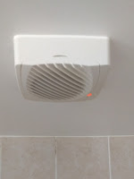
| The ventilator. Just in case you were wondering... |
From the start this thing had the problem of being quite loud. The other family members very much preferred it to stay off while relaxing in the bath. Over time their wish was gradually granted as the fan got more and more slow and finally stopped turning altogether.
Naturally I took the thing apart and checked the motor. Even when hooking it up to mains directly (and yes, it was a 240V part) it did not run anymore. So I got thinking what to do next.
A simple plan
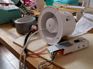
Since the warranty had already run out by a few weeks (duh), I was free to do what I wanted. I figured I could install a new fan as far away from the bathroom as possible in the exhaust chimney thingy on top of the bathroom's roof. So I bought a simple 240V on/off ventilator of similar wattage as the old fan that fitted in the chimney pipe. I would run the wire through the pipe, hook it up to the ventilator controller, and Bob would be my uncle. Easy.
But Murphy was not to be outdone by Bob. While I was thinking this through, buying the ventilator and planning this job, the old ventilator unit failed completely. The flaps no longer opened and the little indicator light stayed dark when running the shower.
Circuit debugging
 |
| The circuit. Note the triac (next to the lamp), and the yellow filtering cap. |
While I am not the most experienced circuit debugger, I know it involves sticking a multimeter in a live circuit. But since this circuit is directly hooked to mains, I would be competing for a Darwin award that way. So I had to try to figure this out without power.
The only semiconductor in the "240V on" part of the circuit was the Z0103 triac. Some probing with my multimeter also seemed to suggest it was not 100% happy anymore. So I ordered a replacement and let things rest until the new part arrived.
Replacing the triac made the light come back on and the shutters work again! Success! So I did a little dance, kissed my wife, and connected the new fan motor. Disappointment! It showed the same not-really-turning-over behaviour as the old one did towards its end. Clearly something was still wrong with the controller board.
More circuit debugging
Further poking around identified another component in the 240V part of the system: a 0.22μF filter capacitor. For lack of a better idea I took it off and put it in my little component tester: 33nF, about a factor 7 too low. So I ordered a replacement and put the whole lot aside while waiting for the mail.
After I soldered the new cap in the circuit, the new motor ran smoothly. Hurray! So I finally was ready to start installing the new fan.
Finale
 |
| It works! Note the piece of paper lifted by the air flow, the new orange capacitor peeking through, and the flange still being attached to the new fan. |
First step was to remove the old fan from the ventilator housing and change the wiring a bit. While messing with the circuit I had removed the original connectors since they seemed flaky, so everything is now either soldered or attached with screw terminals.
Next step was installing the new fan. In principle the new fan just fitted in the top part of the chimney, except that it had a flange. While very useful for the scenario where I would do what the installation instructions say, I was not planning to do that. Fortunately a plastic flange is no match for me and my hacksaw.
 |
| The fan attached to the (upside-down) chimney top. Note the two bolts that just allow the fan to turn. |
I then drilled two holes through the chimney top and the pipe around the fan, while taking care not to get in the way of the fan blades. Through the holes went two flat head bolts, and on the bolts went two nuts that I secured with a tiny drip of super glue. The top actually has an inner and an outer pipe. The inner one goes inside the chimney, while the outer sits on the outside. The fan is bolted to the inner pipe. The heads of the bolts were flat enough not to stop the top to go inside the chimney pipe. So I ran the wire through the chimney, put the top back on the roof, and went downstairs into the bathroom to hook things up.
Inside, things were straightforward in concept. But trying to get a bunch of wires to fit under the cover, the cover to be against the ceiling, 4 screws to through 4 holes, and somehow have a hand left over to fasten the screws above my head was somewhat tricky to say the least. And of course I had to repeat the exercise because I found I had to tweak the two potmeters a bit after the first test run.
But all is well that ends well. The ventilator works again, and is noticeably more quiet than before. However, in the future I might still add a switch so my wife can enjoy her bath in absolute silence if she is so inclined.
 |
| The orignal (non-working) fan. The brown part in the front-right is a bi-metal actuator to open the flaps. |
 |
| Good cap. |
 |
| Bad cap. |
 |
| Removed the original fan. Note the feed-through for the new fan's wire fixed in place with some hot glue. |
 |
| The new fan in the upside-down chimney top. The wire will run through the chimney pipe and connect to the controller in the orignal casing. |
